
New Sewer Connection
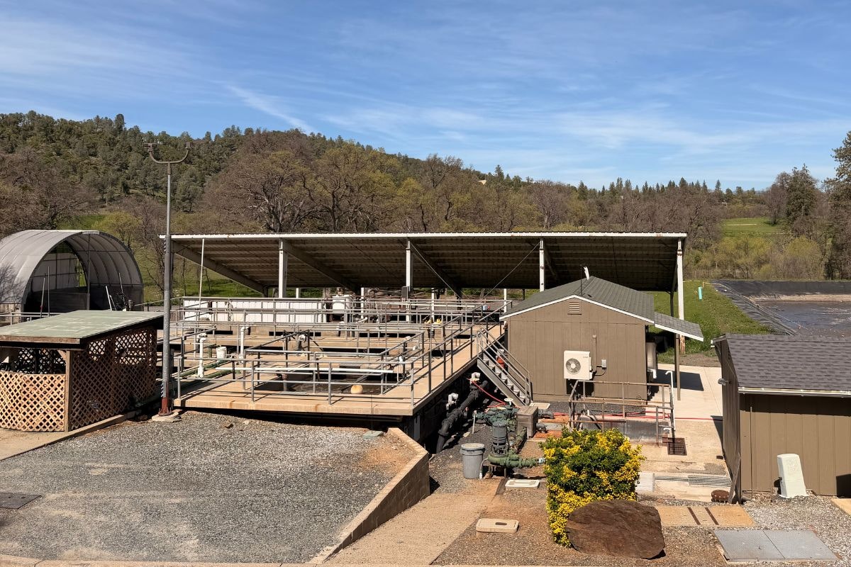
The GCSD is responsible for Wastewater Collection for approximately 1,500 residents of the Groveland and Big Oak Flat communities. The Wastewater Collection System includes 16 sewage lift stations, 35 miles of gravity mains, 7 miles of force mains, a recycled water treatment plant, 2 surface storage reservoirs, and approximately 15 acres of spray fields.

If you see a sewage spill occurring, please call 209-962-7161 immediately. Members of the Collection & Distribution team are available at all times for emergency response.
Sewage spills occur when the wastewater being transported via underground pipes overflows through a manhole, cleanout or broken pipe.
Common Causes of Sewer Spills
Grease builds up inside and eventually blocks sewer pipes. Grease gets into the sewer from household drains, as well as from poorly maintained commercial grease traps and interceptors.
Structure problems caused by tree roots in the lines, broken/cracked pipes, or missing/broken cleanout caps.
